 ru
ru
products categories
- Battery Production Equipment Line
- Battery Lab Pilot Equipment Line
- Lithium Battery Pack Assembly Line
- Solid State Battery Assembly Line
- Sodium Ion Battery Production Line
- Supercapacitor Assembly Line
- Lithium Ion Battery Recycling Plant
- Dry Electrode Preparation Solution
- Perovskite Based Solar Cell Lab Line
- Li ion Battery Materials
- Cathode Active Materials
- Anode Active Materials
- Customized Battery Electrode
- Coin Cell Parts
- Lithium Chip
- Cylindrical Cell Parts
- Battery Current Collectors
- Battery Conductive Materials
- Electrolyte
- Metal Mesh
- Battery Binder
- Separator and Tape
- Aluminum Laminate Film
- Nickel Strip
- Battery Tabs
- Graphene Materials
- Nickel Felt
- Titanium Fiber Felt
- Battery
- Battery Pack Machine & Compoments
- Battery Pack Compoments
- Turnkey Solutions Battery Pack Assembly Line
- Cell Sorter
- Battery Pack Spot Welder
- Laser Welder
- Battery Charging Discharging Tester
- Battery Pack Aging Machine
- Battery Pack Comprehensive Tester
- CCD Visual Inspector
- Battery Pape Sticking Machine
- BMS Testing Machine
- Al Wire Bonding Machine
- Lithium Battery Machine
- Battery Tester & Analyzer
- Battery Safety Tester
- Battery Material Tester
- Rolling Press Machine
- Spot Welding Machine
- Vacuum Mixer Machine
- Crimping/Disassembling Machine
- Vacuum Sealing Machine
- Electrolyte Filling
- Stacking/Winding Machine
- Electrode Cutter/Slitter
- Pouch Forming Machine
- NMP Solvent Treatment System
- Lithium Battery Production Plant
- Vacuum Glove Box
- Furnaces
- Coaters
- Hydraulic Press
- Ball Mill
- Planetary Centrifugal Mixer
- Laboratory Machine
- Metal Foam
contact us
- If you have questions, please contact us, all questions will be answered
- WhatsApp : +86 13003860308
- Email : David@tmaxcn.com
- Email : Davidtmaxcn@gmail.com
- Add : No. 39, Xinchang Road, Xinyang, Haicang Dist., Xiamen, Fujian, China (Mainland)
-
 Cylindrical Cold Press Mould for Hydraulic Press
The cylindrical mold is a common tablet pressing mold in the laboratory powder sample pressure molding, which is suitable for the molding and testing of most powder samples in the laboratory. The mould is exquisite in workmanship, reasonable in design and convenient in operation. With the use of tablet press, powder sample materials can be pressed into shape, such as circular sheet, cylinder, etc. the sample size depends on the mold size ordered by users; the mold is widely used in battery, superconductor, cement, ceramics, catalysis, silicate, powder metallurgy, sea mud analysis, biochemical analysis and new material sample preparation research and development. In addition, the product can also be used with calcium iron, infrared, X-ray fluorescence and other testing instruments.
-
 300℃ 12T Manual Lamination Hot Press with Double Heating Plate
Laboratory Electronic Industry RT-300c Widen Flat Automatic Hot Press Machine
-
 500℃ 12T Electric Compact Lamination Hot Press with Double Heating Plate
Laboratory Electronic Industry RT-300c Widen Flat Automatic Hot Press Machine
-
 Hydraulic Electric Roll to Roll Press Machine for High-precision Rolling of Battery Electrode
Roll Sublimation Heat Press Roller Machine For Li ion Battery Pole Piece Rolled
-
 5V6A 256 Channel Pouch Cell Hot Press Pressure Formation Machine
5V6A 256 Channel Pouch Cell Hot Press Pressure Formation Machine 1. Brief introduction of equipment function The equipment is mainly used for the formation of pouch cell under pressure. The whole machine consists of 1 heat preservation box and 3 sets of clamps, among which the equipment has 256 channels, and the fixture and equipment are integrated. The main functions of the fixture are as follows: 1) The pressure required for pressing the cell is provided, which can be set arbitrarily within the allowable pressure range. If the pressure setting exceeds the pressure setting range, an alarm will be given; 2) Press the electrode tightly to ensure the reliable connection between the electrode and the circuit of the whole machine. 3) Make sure that the battery is upright and the air bag is upward. 2. The main functions of formation are as follows:1) Heating and temperature control function; 2) Channel reliable docking function; 3) Charging function; 4) Discharge function; discharge energy feedback to power grid; 5) Data link and communication function; 6) Safety and protection functions. 2. Basic parameters Configure power supply Voltage AC380 ± 10%, rated power 18kw. Air source input The minimum input air pressure shall not be less than 0.6MPa, and the maximum input air pressure shall not exceed 1.0MPa. There are three clamps in the whole machine. A single clamp is pressurized by a cylinder with a diameter of 250mm. When the air source input reaches 0.6MPa, the maximum pressure of a single cylinder is 3000kgf. Equipment weight Fixture weight<300kg, machine weight<1300kg, the ratio of total weight to bearing area<500kg/m² Main color of appearance Warm grey 1C. Overall dimension of equipment long × wide × Height ≤ 2000mm × 800mm × 2348mm (height 2030mm after removing cylinder) The dimensions of the incoming cell (air bag width ≤ 50mm) Length: 10-155mm Width: 10-105mm The length and width dimensions of the cell include the edge sealing dimensions of the aluminum laminated film. Pass rate ≥98% 3. Machine specifications Fixture Each fixture is divided into 22 layers of heating plate, and there are heat insulation measures between the heating plate and the fixture. Each layer of heating plate is equipped with a temperature probe, PLC can inspect the temperature probe of each layer of heating plate, and display the temperature detection value on the touch screen. Control mode The equipment is controlled by PLC: it can set the heating target temperature. The equipment can control the heating plate according to the target temperature, and timely protect and alarm when the heating plate overtemperature occurs. Heating temperature Temperature control precision of each layer of heating plate ± 3℃ Pressurization control PLC can realize the multi-stage pressure control of the fixture, and the pressure control precision can reach ± 25kg, accurately control the cylinder pressure through the pressure sensor. Cell measurement The four wire method is used to measure the current and voltage of the cell. The circuit connection between the fixture and the device is realized by a special PCB. The electrode plate is installed on the device, and the battery is compressed by the upper and lower pressing plates. At the same time, the fast and reliable connection between the device and the fixture circuit is realized. security Thermal insulation measures shall be taken for the peripheral doors and observation windows of the equipment. The equipment is equipped with security access control to ensure more safe and reliable use of the equipment. Setting range of charge discharge voltage Charging voltage setting range: 0mV~5000mV (resolution 1mV); Discharge voltage setting range: 2000mV~5000mV (resolution 1mV). Charging and discharging current setting range: 10mA~6000mA (resolution 1mA)。 Measurement control accuracy Voltage measurement control accuracy: ±(0.1%FS+0.1%RD) Current measurement control accuracy: ±(0.1%FS+0.1%RD) Time measurement control accuracy: ±(0.1%FS+0.1%RD) Control precision of voltage measurement ±(0.1%FS+0.1%RD) Control accuracy of current measurement ±(0.1%FS+0.1%RD) Control precision of time measurement ±(0.1%FS+0.1%RD) End condition of charge and discharge Constant current charging (CC): end conditions are voltage, time and capacity Constant current and constant voltage charging (CC-CV): end conditions are current, time and capacity Discharge method: the end condition of constant current discharge (DC) is voltage, time or capacity Main functions of the software 1. According to time, voltage, current and other parameters to control the end conditions of the process; 2. Calculate the charging capacity parameters of the formed battery; 3. Editing and management functions of charging and discharging process: 4. Up to 32 step parameters can be set; 5. Up to 256 cycles can be set; 6. Each step can be selected by constant current charging, constant current and constant voltage charging, shelving, constant current discharging, cycle and other attributes; 7. The edited process file can be archived for future use. 8. The charging current can be set from (10~6000)mA, the charging voltage can be set from (0~5000)mV, the discharge voltage can be set from (2000~5000)mV, and the time of each step can be set from 1min~1000min. 9. Software security control: 11.1. The running data and curve of each point can be automatically saved after the set step is run, and the software has a capacity alarm function; 11.2. Overcharge protection: When the voltage exceeds the overcharge protection setting value, the flow of the channel is stopped, and the setting value can be set; 11.3. Capacity over-tolerance protection: When the capacity of the battery cell exceeds a certain range, the flow of the channel will be stopped; It can sort the formed batteries and is equipped with indicator lights. The sorting method can be set as: capacity, time, open circuit voltage, average voltage, fixed-point voltage, etc. 11.4. The charge and discharge data of each battery can be formed into a data list form for users to view or print out. The equipment supports barcode recognition function, and can realize the one-to-one correspondence between battery and channel and record production data. System protection function 1. Over-current, under-current, over-voltage, under-voltage, and over-capacity protection: the upper and lower limits of battery voltage, current, and capacity can be preset in the process. When the limit conditions are reached, the system will automatically force the battery to sleep, and The software interface prompts failure. 2. Leakage current protection: When the working status is inspected for more than 200mA leakage current more than three times, turn off the input power of the switching power supply. 3. Charging over-voltage protection: When the battery is inspected by the system during battery charging, when the battery voltage is higher than the upper limit voltage, the battery will stop charging. 4. Discharge under-voltage protection: When the battery is inspected by the system during battery discharge, when the battery voltage is lower than the lower limit voltage, the battery stops discharging. 5. Equipment power failure protection: when the equipment is abnormally powered off, it can continue to execute the current process step; it has the function of registering the abnormal channel; Three color alarm light (with sound and light) Waiting (the process is finished)-yellow light; The process is in progress (sleeping, charging, discharging)-green light; System failure (over temperature, hardware failure, etc.)-red light and sound Basic configuration of the whole system 1. The temperature rise of the drive board and the internal heat sink of the switching power supply on the equipment is ≤30℃, and the dissipation power of the heat sink should be designed according to the long-term full scale to ensure that the equipment can work stably for a long time. 2. The equipment calibration cycle is 3 months. Within 3 months after the equipment is calibrated, ensure that the voltage measurement and control accuracy of all channels is ≤±(0.1%FS+0.1%RD), and the current measurement and control accuracy is ≤±(0.1%FS+0.1%RD). 3. Electrical part cooling method: fan exhaust cooling. Equipment environmental requirements 1. Working environment temperature: 25±8℃; 2. Relative humidity: 30%~75%; 3. Equipment ventilation requirements: There should be no obstructions within 1.5 meters from the front and rear of the equipment and 0.8 meters from the side of the equipment. 4. Installation location: indoor, clean workshop. 5. Computer configuration: each computer manages 5 sets (provided by the buyer). 4. The equipment's process action flow: control start---cabinet door manually open---fixture open---cell load to the cabinet---fixture tightening---cabinet door close---formation start---formation completion ---The cabinet door is opened---The fixture is opened---The battery cell is placed in the cabinet.
-
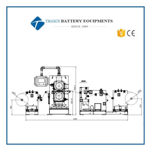 Battery Hot Calender Electrode Rolling Press Machine for Pilot Line
Battery Hot Battery Calender Electrode Rolling Press Machine for Pilot Line 1.Introduction 1.1 Function: This battery electrode sheet continuous rolling production line is used in the rolling process of lithium-ion battery pole piece production to realize the continuous rolling production of battery pole piece coils and meet the specifications and quality required by the battery pole piece process; 1.2 Equipment composition: It mainly includes unwinding device, belt connecting device, edge trimming device, dust removing and iron removing device, heating roller press, belt connecting device after pressing, winding device, hydraulic system, drive control system, disassembly roller device, etc; 1.3 Schematic diagram of equipment layout (the picture shows the right type, and the left type is symmetrical to it): 2.Process parameters 2.1 Application: Suitable for the rolling process of battery materials such as lithium iron phosphate, lithium cobalt oxide, lithium manganate, ternary, lithium titanate, etc. 2.2 Adapt to incoming material specifications: pole piece width 150~300mm, material roll diameter ≤500mm 2.3 Output product indicators: 2.3.1 Thickness uniformity of pole piece after rolling: ≤±0.002mm (required thickness accuracy of incoming material: ≤±0.002mm); 2.3.2 Alignment error of winding edge: ≤±0.3mm 3.Installation 3.1 The main engine part requires ground load ≥ 3.5t/㎡ (or base on the provided foundation drawing) 3.2 Power supply: 380V±5%, 50Hz three-phase five-wire system 3.3 Total power: 60kW+10% safety factor/unit 3.4 Compressed air: pressure 0.2~0.7MPa, flow rate: 20L/min, the outer diameter of the interface pipe is 8mm 3.5 Operating environment: temperature range 0~+45℃ relative humidity: ≤30% 3.6 The inner diameter of the barrel: 3inch, the length of the barrel ≤550mm 4. Equipment function index 4.1 Overall dimensions of the continuous rolling line (length*width*height): 4.8×2.6×2 m 4.2 Total weight of equipment: about 9 tons 4.3 Appearance color of the equipment: national standard warm gray 1C 4.4 Arrangement: left/right (the power drive part is on the left/right when viewed from the feed end) 4.5 Rolling speed: 1-12m/min 4.6 Maximum pressure between rollers: 1800kN 4.7 Overall equipment efficiency: OEE≥95% 4.7.1 Calculation formula: OEE = availability rate × performance × product qualification rate 4.7.2 Sub-indices Related sub-indices Note Availability = operating time ÷ planned working time 98% Utilization rate Expressiveness = total output ÷ (operating time min*CPM) 98% Equipment capacity Product qualification rate = actual number of good products ÷ planned number of good products 99% Note: When calculating, deduct the factors that affect normal production such as material supply, power supply, gas supply, etc. 4.8 Design and manufacturing regulations and standards: in line with relevant national standards 5.Main performance indicators 5.1 Unwinding device l Function: Passively provide pole pieces for rolling under certain tension control l Unwinding inflatable shaft: Φ74mm with inflatable gun l Effective use length of inflatable shaft: 550mm l Tension adjustment (setting) range: 1~20kgf l Tension control accuracy: 5% l Correction control: infrared photoelectric correction l Correction stroke: ±50mm l Edge control: deviation correction accuracy is ≤±0.2mm l Magnetic powder brake: 50Nm 5.2 Front connecting device l Function: Used to connect the pole piece when it breaks during the rolling process or when changing the material roll to reduce the waste of pole piece. l Composition: It is composed of connecting plate, pressure rod, air cylinder, guide roller and other parts. l Control: the cylinder is controlled by the manual pneumatic valve to compress and loosen the pole piece l Operation: manual connection 5.3 Edge trimming device l Function: Used to cut off the uncoated foil on both sides of the pole piece, reduce the wrinkles of the pole piece caused by the inconsistent elongation rate during rolling, and reduce the scrap rate caused by the pole piece strip. l Principle: The upper cutting blade is manually fed, relying on the knife, and the left and right cutting knives are controlled separately. l Drive: 0.55KW variable frequency motor drives the lower cutter shaft to be consistent with the rolling speed l Slitting speed: the slitting speed is synchronized with the rolling of the main machine l Upper cutting blade: Φ100×Φ65×1.2mm l Cutting blade: Φ100×Φ65×2mm 5.4 Dust removal device l Function: Clean up the dust and burrs on the pole piece l Composition: consists of front and rear roller brushes, air cylinders, vacuum cleaners, roller brush drive motors, etc. l Principle: Use front and rear roller brushes to brush down the dust and burrs on the pole pieces, pass the dust suction bucket, the dust and air are separated by the cyclone separator, and the clean air is discharged from the muffler through the fan. Clean the dust regularly. l Number of roller brushes: 2 l Drive: 0.75KW high pressure fan drive l Processing air volume: 2.4 m3/min 5.5 Front damping device l Function: reduce the jitter of the pole piece during the rolling process and prevent the strip from breaking l Composition: fixed guide roller, floating guide roller, fixed bracket, etc. l Principle: The pole piece passes through the floating guide roller to reduce the jitter of the pole piece and prevent the pole piece from being stripped. 5.6 Roller press l Structure: Two rollers are arranged horizontally up and down l Frame: "mouth" type casting arch l Bearing seat: 45 cast steel l Base: overall base l Roll size: φ400mm×450mm l Roll material: 9Cr3Mo (electroslag remelting) l The depth of the quenched layer of the roll surface: ≥18mm, the roll is quenched and tempered HB280-300. l Roll surface roughness Ra≤0.2um l Roll cylindricity≤±0.001mm l Tolerance of radial runout of roll assembly machine: ≤±0.002mm l Heat roller structure: solid roller with heating hole l Heating connection mode: the shaft end is connected by RHG rotary joint l Roll heating method: mold temperature heating controller l Heating medium: heat transfer oil l Heating temperature: room temperature~120℃, continuously adjustable, controlled by digital display temperature controller l Roll surface temperature uniformity error (working surface): ≤±1℃ l Adjustment accuracy: ±0.5℃ l Heating speed: heating from room temperature to 80℃, heating ≤100 minutes; heating at room temperature to 120℃, heating ≤150 minutes l Heating power: 45kW l Preset line pressure of roller press: 5t/cm l Roll gap adjustment range: 0-2mm, touch screen display. l Roll gap adjustment: Servo motor drives the middle wedge to adjust through the ball screw l Adjustment accuracy: 0.001mm l Maximum pressure between two rollers: 1800KN (pressurized by gas-liquid booster pump) l Drive: The geared motor is connected to the rolls through the elastic pin connector, and the rolls are driven by gears l Main motor power: 7.5KW (380V 50HZ variable frequency speed regulating motor) l Rolling speed: 1-12m/min (stepless speed regulation) l Electrical control: PLC program control, touch screen operation. l Work pressure: gas-liquid booster pump l Pressure method: lower hydraulic cylinder and upper pressure l Hydraulic cylinder diameter: φ220mm l Hydraulic system: the maximum pressure is 31.5MPa. l Host device size: (length × width × height) about 2800mm × 950mm × 1930mm l Arrangement: Left/Right (the power-driven part on the left side of the feed end is the left type, and the right side is the right type) l Appearance of equipment: The color is international standard warm gray 1C or customized according to customer requirements l Host weight: about 6 tons 5.7 Rear vibration damping device l Function: reduce the jitter of the pole piece during the rolling process and prevent the strip from breaking l Composition: fixed guide roller, floating guide roller, fixed bracket, etc. l Principle: The pole piece passes through the floating guide roller to reduce the jitter of the pole piece and prevent the pole piece from being stripped. 5.8 Winding device l Function: Collect the rolled pole pieces into coils l Composition: Inflatable shaft, deviation correction, magnetic powder clutch, winding reducer, frame, etc. l Principle: After rolling, the pole pieces are collected into coils, and the edges of the coils are neatly controlled by the correction mechanism. l Rewinding inflatable shaft: Φ74mm with inflatable gun l Effective use length of inflatable shaft: 550mm l Tension adjustment (setting) range: 1~20kgf l Tension control accuracy: 5% l Correction control: infrared photoelectric correction l Correction stroke: ±50mm l Edge control: deviation correction accuracy is ≤±0.2mm l Magnetic powder clutch: 50Nm l Winding power: 1.5KW reduction motor 5.9 Drive control system l The drive of each component of the entire continuous rolling production line is driven by motors of different specifications and models, which are centrally operated on the operation panel, and all drive motors are equipped with overload protection; l The control part includes: touch screen, PLC, main motor inverter, roller gap servo motor driver, tension controller, correction controller, etc. l The operation of the system adopts PLC control, touch screen and button operation mode, and emergency stop buttons are provided at the suspension operation station, the rolling mill feed end, and the winding and unwinding operation end to ensure the safety of the operator l The main control items of the system include: l Roller press start, stop, indication, overload protection l Hydraulic system start, stop, instruction l Rolling speed setting, speed display l Pressure setting, pressure display l With roller pressure parameters (pressure, roller gap) clearing and memory function l Rolling parameters can be automatically restored according to the pole piece model l Meter counting function l Abnormal alarm function l Equipped with MES data output docking function, docking method and database collection method are provided by the buyer 5.10 Roller disassembly device l Function: This device is used for roll replacement or maintenance, reducing the operation time of disassembling rolls and reducing the labor intensity of operators l Composition: consists of a roll-removing bracket, a roll-removing guide rail, etc. l Operation: When disassembling the roll, push the roll and the chock out of the dismounting guide rail, and use a crane or forklift to disassemble the rolls and transport them out. The installation is carried out in the opposite steps. 6.Configuration list No. Name Brand/Model Note 1 Roller Xingtai Sinosteel Certificate of conformity 2 Bearing Bush / Luo shaft 3 Reducer Boneng/Guomao 4 PLC Siemens/Delta 5 Touch screen Siemens/Delta 6 Frequency converter Siemens/Delta 7 Roll gap adjustment servo system Siemens/Delta 8 Electrical components Schneider, Chint 9 EPC Aibo/Timaco 10 Gas-liquid booster pump United States AZ 11 Pneumatic Components Airtac/SMC Air pipe is blue 7.Spare parts list No. Name Quantity Unit Note 1 Doctor blade 4 pcs 2 Upper cutter blade 2 pcs 3 Lower cutter blade 2 pcs 4 Hydraulic line seals 2 set 5 Roll changing accessories 1 set 1 set per workshop 6 Simple equipment maintenance tool 1 set Toolbox 8.Consumable parts list No. Name Specification Quantity Brand Reference replacement cycle 1 Doctor blade 0.2*30*450mm 2 Switzerland 15 days 2 Upper cutter blade Φ100*1.2 2 Domestic 15 days 3 Lower cutter blade Φ100*2 2 Domestic 15 days 4 Roller Φ400*450 2 Sinosteel 6 months (Grind) 5 Gear oil VG320 50L Great Wall 12 months 6 Hydraulic oil L-HV150 20L Great Wall 12 months 7 Low friction cylinder 2 Airtac/SMC 2 years 8 Three-axis cylinder 2 Airtac/SMC 2 years 9 Ultra-thin cylinder 4 Airtac/SMC 2 years 10 Pull valve 5 Airtac/SMC 2 years 11 The electromagnetic valve 4 Airtac/SMC 2 years 12 Axial fan 2 2 years 13 Potentiometer 1 Schneider 2 years
-
 Automatic Hot Press Pressure Formation Machine for Pouch Cell Manufacture
-
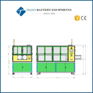 5V20A 64 Channel Vertical Pouch Cell Hot Press Pressure Formation Machine For Pouch Cell Production Line
-
 Manual Flat Hydraulic Hot Pellet Press with Double Plate 300C or 500C
Manual Flat Hydraulic Hot Pellet Press with Double Plate 300C or 500C
-
 300C 500C Lab Manual Cylindrical-electric Hydraulic Hot Pellet Press
300C 500C Lab Manual Cylindrical-electric Hydraulic Hot Pellet Press
-
 300C 500C 24T Lab Manual Flat Heat Hydraulic Press with Double Heating Die
300C 500C 24T Lab Manual Flat Heat Hydraulic Press with Double Heating Die
-
 15T 30T Mini Four Column Manual Powder Tablet Hydraulic Press
15T 30T Mini Four Column Manual Powder Tablet Hydraulic Press
-
 Lab Widened Manual Integrated Hot Hydraulic Press with Double Heating Plates 300C 500C
Lab Widened Manual Integrated Hot Hydraulic Press with Double Heating Plates 300C 500C
-
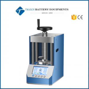 Laboratory Intelligent -automatic Powder Tablet Press with Programmable Controller 20T to 100T
Laboratory Intelligent -automatic Powder Tablet Press with Programmable Controller 20T to 100T
-
 300C 500C 40T Lab Flat Automatic Hydraulic Hot Press with High Precision Pressure Control
300C 500C 40T Lab Flat Automatic Hydraulic Hot Press with High Precision Pressure Control
 Cindy@tmaxcn.com
 David@tmaxcn.com
 +86 13003860308
 18659217588